dsap Diagnostic Cable Instructions
Purpose
Use this Windows-only guide to connect the diagnostic cable to a running device and open a read-only serial-monitoring session. This guide ends when the terminal connection is open. It does not describe device settings, status messages, or diagnostic procedures.
Prerequisites
Before starting, have the following available:
- A completed diagnostic cable.
- A Windows laptop with an available USB-A port and internet access.
- The device to observe.
- Either Tera Term or PuTTY installed on the Windows laptop.
The cable uses a Silicon Labs CP210x USB-to-UART bridge. Install the CP210x VCP driver for Windows before connecting the cable. Follow the installer or driver package instructions supplied by Silicon Labs.
For cable background and specifications, see the Adafruit USB-to-TTL serial cable.
1. Verify the Cable Assembly
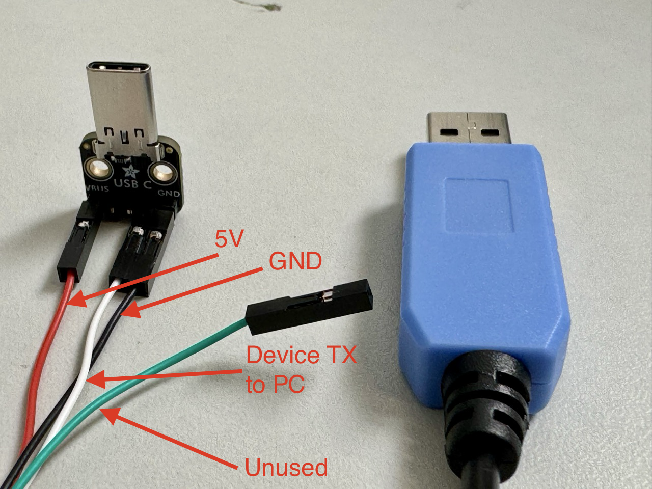
The cable is a read-only serial monitor. Verify that its leads match the annotated photo:
| Lead | Connection and use |
|---|---|
| Red | 5 V charging power. Leave it connected to charge the device. Disconnect it before connecting the cable when observing a device without charging it. |
| Black | Ground. Leave it connected. |
| White | Device TX to PC. Leave it connected to observe device activity. |
| Green | Unused. Leave it disconnected. |
2. Connect the Cable and Find Its COM Port
2.1 Confirm USB-C Orientation
When plugging the cable into the device, make sure the orientation of the USB-C board matches the photos below.
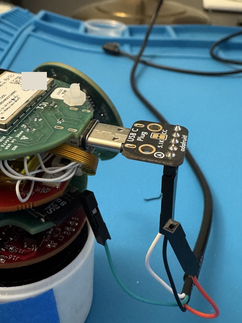
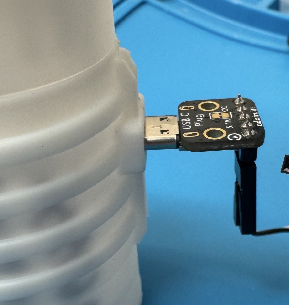
2.2 Connect the Cable and Find Its COM Port
- If you want to observe the device without charging it, disconnect the red 5 V lead first. Otherwise, leave the lead connected.
- Insert the diagnostic cable's USB-C connector into the device.
- Connect the USB-A connector to the Windows laptop.
- Open Device Manager, then expand Ports (COM & LPT).
- Find the entry for the Silicon Labs CP210x USB-to-UART bridge and
record its COM port number, such as
COM7.
If the CP210x entry does not appear, disconnect the cable, confirm the driver installation completed, reconnect the cable, and check Device Manager again.
3. Open the Serial Connection
Use one of the following terminal applications. In either application, select the COM port found in Device Manager and use these settings:
| Setting | Value |
|---|---|
| Speed | 57600 baud |
| Data bits | 8 |
| Parity | None |
| Stop bits | 1 |
| Flow control | None |
Option A: Tera Term
- Download and install Tera Term from the official Tera Term release page.
- Start Tera Term. In the New connection dialog, select Serial and choose the recorded COM port.
- Select Setup > Serial port.
- Set the speed to
57600and confirm the remaining values match the serial settings table above. - Select OK to open the serial-monitoring session.
Option B: PuTTY
- Download and install PuTTY from the official PuTTY download page.
- Start PuTTY and select Serial as the connection type.
- Enter the recorded COM port in Serial line and enter
57600in Speed. - Select Connection > Serial. Confirm that data bits are
8, stop bits are1, parity is None, and flow control is None. - Return to Session and select Open to open the serial-monitoring session.
The serial connection is now initialized. Continue with any applicable Sonogen diagnostic procedures.