dsap Flashing Instructions (production)
dsap operator use is Windows-only. For command details and developer
troubleshooting, see dsap Flashing Instructions
(development).
Purpose
Use these instructions on an Assembly Laptop to:
- Flash firmware to the MSP430 MCU.
- Upload the device certificate bundle to the SARA module.
- Calculate the gel sensing threshold and set the final device parameters during production.
Prerequisites
Before starting, confirm:
- The Assembly Laptop has completed the dsap Setup Instructions, including BioT API access and MSP430 Flasher installation.
- The assembled device is ready for flashing.
- The traveler or work order identifies the required firmware version.
- The Transducer Characteristics Reference is available for Envelope Voltage lookup by transducer serial number.
Run the commands below in Windows PowerShell. Complete each command successfully before proceeding to the next step.
Equipment and Materials
Confirm the following equipment and materials are available:
| Quantity | Equipment Number | Description |
|---|---|---|
| 1 | EQT-0001 | Assembly Laptop |
| 1 | EQT-0009 | Flash Module |
| 1 | EQT-0010 | Rainbow Cable |
| 1 | EQT-0011 | MSP-FET (Flash Emulation Tool) |
| 1 | EQT-0012 | USB Programming Cable |
| 1 | SON-0901 | Assembled Device |
Flashing Module Switches
Use these Flash Module switches for each operation:
| Operation | Switch |
|---|---|
| MCU flashing | U2 |
| Certificate upload | U3 |
| Parameter setting | U4 |
1. Flash the MCU Firmware
1.1 Prepare the Hardware
- Boot the Assembly Laptop into Windows.
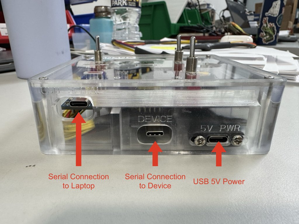
- Connect a USB-C power supply to the 5V Power input on the front of the Flash Module.
- Connect the USB-A cable from the MSP-FET to the Assembly Laptop. Ensure this is the only MSP-FET connected to the laptop.
- Connect the 14-pin connector from the MSP-FET to the port on the top of the Flash Module.
- Connect the Flash Module to the assembled device using the Rainbow Cable with the orientation shown. When the cable is properly connected, the device should start slowly flashing a green LED.
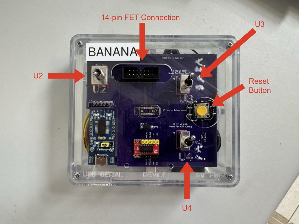
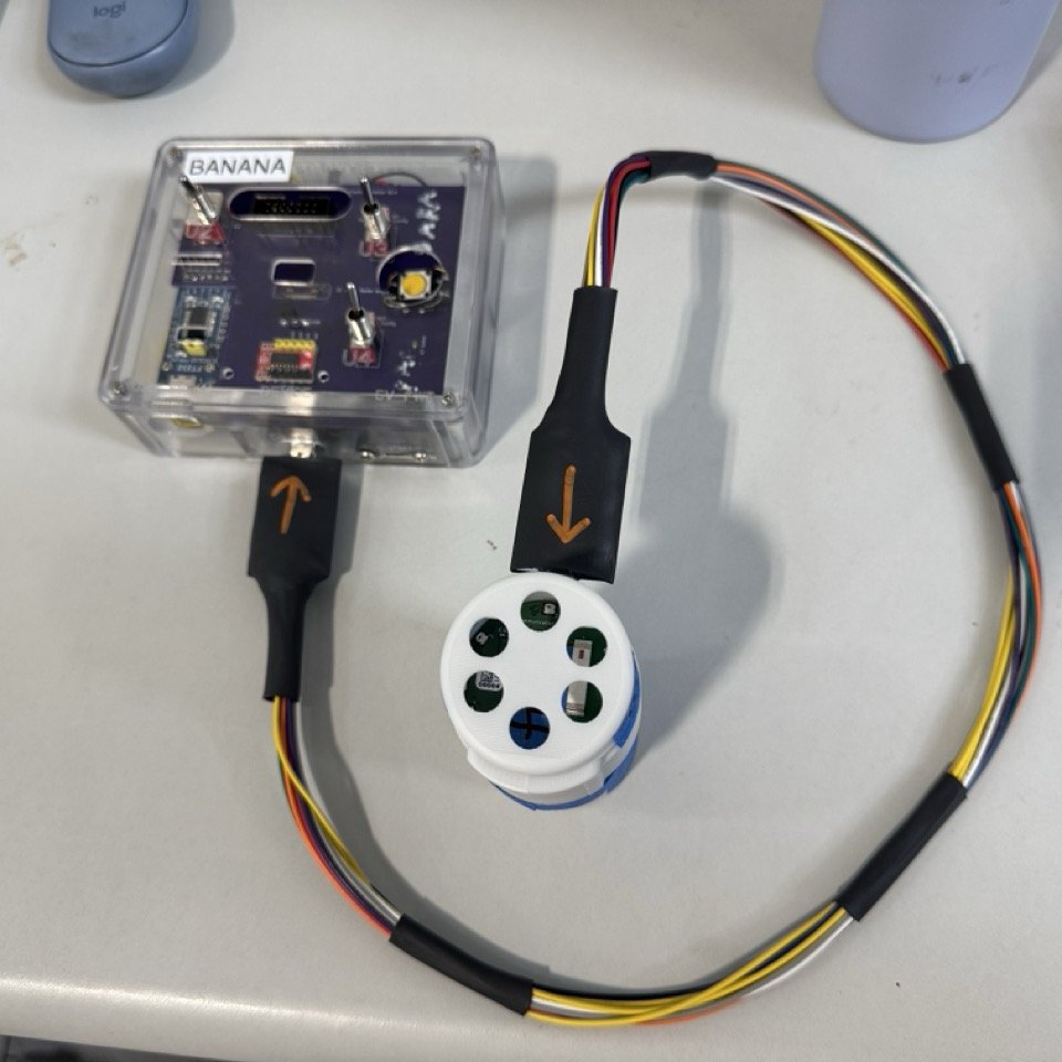

Operator STOP: Before continuing, stop and set flashing
module switches U2, U3, and U4
up. Do not continue until all three switches are up.
1.2 Run dsap mcu
Flash the MCU with the latest firmware version:
If the traveler or work order specifies an alternate bundled firmware
version, replace <VERSION> with the specified semantic version:
Use beta or release candidate firmware only when the exact prerelease
tag is specified. Do not use --local-fw unless the traveler, work
order, or engineering deviation names the local firmware file to flash.
After successful flashing, record the reported firmware version on the traveler.
2. Generate the Serial Number and Certificate Bundle
Run:
Follow the prompts and record the device serial number on the traveler. The bundle path and Device UID are not traveler records.
3. Upload Device Certificates
3.1 Prepare the Hardware
- Disconnect the 14-pin MSP-FET connector from the Flash Module.
- Disconnect the MSP-FET USB-A cable from the Assembly Laptop.
- Connect a USB data cable from the Assembly Laptop to the USB-C serial port on the front of the Flash Module.
Operator STOP: Before continuing, stop and flip
certificate upload switch U3 down, then press the reset
button, then flip U3 back up. Do not
continue until U3 is back up.
3.2 Confirm the USB Serial Connection
Confirm the MSP-FET is disconnected and the Flash Module is the only
serial device connected to the Assembly Laptop. dsap automatically
selects the sole connected serial device.
3.3 Run dsap sara
Before accepting the offered certificate bundle, verify that its
filename matches the device serial number created and recorded in Step
2. If it does not match, enter n and select the correct bundle in the
file picker.
Confirm SARA configuration successful. before proceeding.
4. Configure Final Device Parameters
4.1 Prepare the Hardware
- Keep the USB Programming Cable connected between the Assembly Laptop and the Flash Module.
- Place the device in the charging stand.
4.2 Run dsap params --gelset
Follow the guided prompts, using:
- The Client ID offered from the certificate bundle, unless the traveler or work order requires a different non-empty value.
- The default setup Gel Sensing Threshold of
50m, unless the traveler or work order specifies otherwise. - The Envelope Voltage from the Transducer Characteristics Reference
listed in Prerequisites, matched to the device's transducer serial
number. Accept
0only when a sham device is required by the traveler or work order.
Record the final displayed Client ID, Envelope Voltage, and calculated Gel Sensing Threshold on the traveler. Complete the remaining prompts, including the verification in section 5.
5. Verify Gel-Pass and Dry-Fail Behavior
Continue following the dsap params --gelset verification prompts.
Confirm both acceptance checks:
- Gel-pass: Blue therapy lights turn on and begin flashing with the device on phantom tissue.
- Dry-fail: The red failure light turns on with the device in the charging stand.
If either check fails, stop and notify Sonogen Development or the station owner. Follow the final CLI prompts to stop and disconnect the device.
6. Final Checks
Before releasing the device from this station, confirm:
- MCU flashing, certificate upload, and final parameter setting all completed successfully.
- Both gel-pass and dry-fail acceptance checks passed.
- The traveler contains the firmware version, device serial number, Client ID, Envelope Voltage, and calculated final Gel Sensing Threshold.
7. Troubleshooting Notes
- For MCU flashing failures, check the authorized firmware version and confirm exactly one MSP-FET is connected.
- For USB serial connection failures, confirm the MSP-FET and any
other serial devices are disconnected and the USB data cable is
connected to the Flash Module's USB-C serial port. For manual
troubleshooting, find the port under Ports (COM & LPT) in Device
Manager and rerun the command with only its number, such as
--port 7forCOM7. - For certificate staging failures, confirm the selected
.zipfilename matches the device serial number created in Step 2. - If the offered Client ID is incorrect, decline it and enter the correct value from the traveler or work order.
- If the MSP-FET is not recognized, MSP430 Flasher is missing, serial number creation fails, or a failure remains unresolved, stop and notify Sonogen Development or the station owner. See the development troubleshooting notes for diagnostic guidance.