dsap Flashing Instructions (development)
These development instructions include help with commands, implementation notes, examples, and troubleshooting detail for developers and maintainers. The production guide keeps required inputs, traveler records, and acceptance checks concise; the CLI prompts provide the detailed guided actions. For the operator production workflow, use dsap Flashing Instructions (production).
Purpose
Use these instructions on an Assembly Laptop to:
- Flash firmware to the MSP430 MCU.
- Optionally create a BioT device object and certificate bundle.
- Load the device certificate bundle into the SARA module.
- Calculate the gel sensing threshold and set final device parameters.
Prerequisites
Before starting, confirm the following:
- You have already completed the dsap Setup Instructions on this Assembly Laptop.
- The MSP-FET or other supported TI flash tool is connected to the target hardware.
- You have the certificate bundle
.zipfile for the device. - You know which bundled firmware version to flash, or you have been
told to use
latest. - You have the Sonogen Transducer Voltage Characteristics reference document with Envelope Voltage values by transducer serial number.
- If you plan to create BioT device objects from
dsap, the optional BioT API setup in the setup instructions is complete.
Flashing Module Switches
Use these Flash Module switches for each operation:
| Operation | Switch |
|---|---|
| MCU flashing | U2 |
| Certificate upload | U3 |
| Parameter setting | U4 |
1. Flash the MCU Firmware with dsap mcu
Use dsap mcu from the Assembly Laptop to select a bundled firmware
version and flash it with the TI flasher utility.
1.1 Prepare the Hardware
- Boot the Assembly Laptop into Windows.
- Connect a USB-C power supply to the 5V Power input on the front of the Flash Module.
- Connect the USB-A cable from the MSP-FET to the Assembly Laptop. Ensure this is the only MSP-FET connected to the laptop.
- Connect the 14-pin connector from the MSP-FET to the port on the top of the Flash Module.
- Connect the Flash Module to the assembled device using the Rainbow Cable with the orientation shown. When the cable is properly connected, the device should start slowly flashing a green LED.
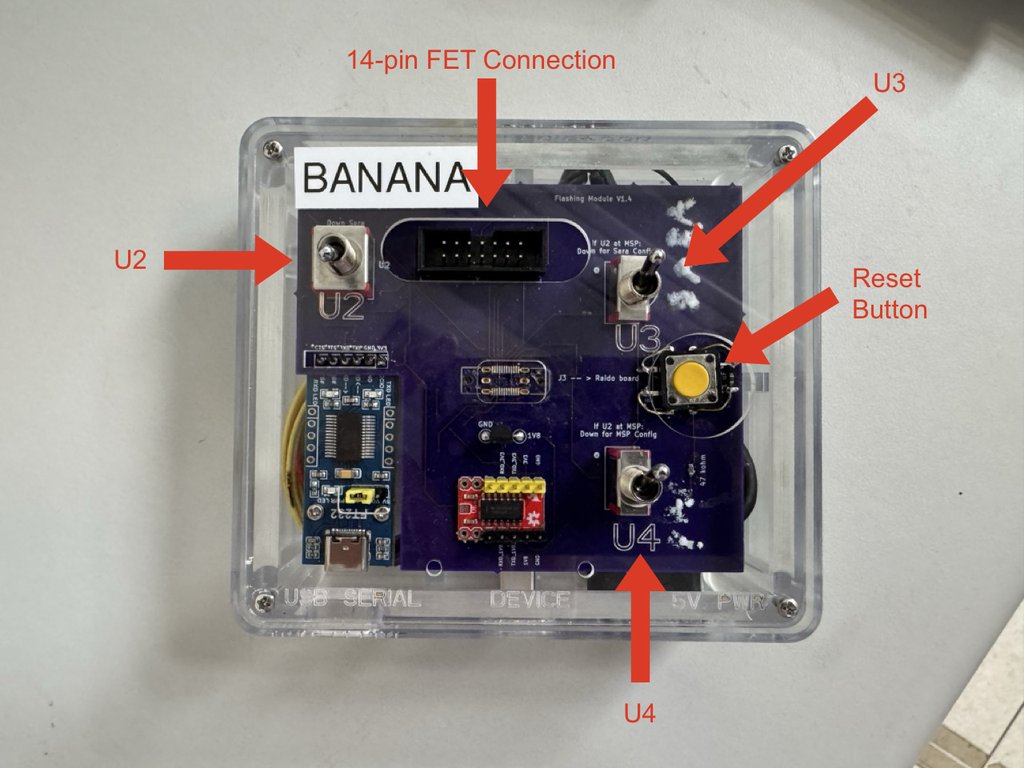
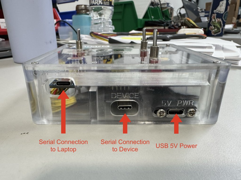
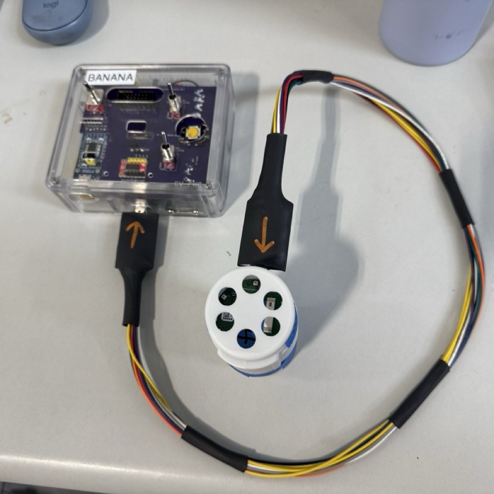
1.2 MSP-FET Selection and Troubleshooting
MSP430 Flasher selects its COM port automatically; you do not need to find or record the port before flashing.
For troubleshooting, you can select the MSP-FET COM port manually with
dsap mcu --port <PORT>. Find the MSP-FET under Ports (COM & LPT)
in Windows Device Manager and pass only the port number: for COM7,
use --port 7. Add --firmware-version <VERSION> to select a bundled
firmware version.
If setup or troubleshooting requires a separate FET compatibility check, open Windows PowerShell and run:
The helper finds the newest standard TI installation, lists connected FETs, and checks FET firmware compatibility. If prompted, select the listed MSP-FET number. This check is optional during normal flashing. If the utility cannot be found, contact the station owner or Sonogen Development.
1.3 Run dsap mcu

Operator STOP: Before running dsap mcu,
stop and set flashing module switches U2, U3,
and U4 up. Do not run the command until all three switches
are up.
Run this command to flash the latest firmware through the single
connected MSP-FET. If the traveler or work order specifies an alternate
firmware version, pass it with --firmware-version instead:
Select an explicit firmware version with --firmware-version. For
troubleshooting, use --port to select the MSP-FET COM port manually:
The value can be a bundled stable release, a bundled prerelease, or
latest (the default). Firmware versions must not use a leading v.
The installed dsap package contains the available releases and reports
the concrete stable version selected by latest.
Normally no --flasher option is needed. Use
--flasher "C:\Path\To\MSP430Flasher.exe" only if MSP430 Flasher is not
under the standard C:\TI\MSPFlasher_* or C:\TI\MSP430Flasher_*
location.
For developer debug builds, pass the local firmware file with
--local-fw and an explicit --firmware-version as the test identifier
printed when flashing succeeds:
--local-fw bypasses bundled-resource checksum verification. Use it
only for local development and debugging, not for production
traveler-driven flashing.
1.4 What dsap mcu Does
When you run dsap mcu, it:
- Resolves the selected firmware from the releases bundled with
dsap, unless--local-fwpoints to a local debug build. - Verifies the size and SHA-256 of bundled firmware.
- Invokes
MSP430Flasher.exe. - Uses automatic USB FET selection unless
--portoverrides it, with the required erase, verification, and power control settings.
1.5 Expected On-Screen Output
You should see status lines similar to:
If the requested firmware version is not bundled, dsap reports a
firmware build error and lists the available versions.
If the flasher utility is missing, you should expect:
Optional: Create a BioT Device and Certificate Bundle
Use dsap serial --create when you want dsap to create the BioT
device object and download the production certificate bundle. Developers
who already have a test certificate bundle, or who are testing only MCU
flashing or local serial-number behavior, may skip bundle creation.
Both forms of dsap serial create a tightly cropped SVG device label at
C:\Users\<USER>\dsap\labels\<serial-number>.svg. The SVG starts on a
624-by-171 design canvas, preserves its aspect ratio, and groups the label
objects so label software can scale the complete label down uniformly. Its
Arial text and information icon are flattened to vector paths, and its QR
code includes a four-module quiet zone. This avoids font substitution and
nested SVG scaling behavior when the label is imported into BarTender.
Example:
When --create is used, dsap authenticates to BioT, creates the
device with the generated serial number as the BioT Unique ID using the
configured service user, refreshes the stored BioT administrator token,
downloads the production certificate bundle to
C:\Users\<USER>\dsap\certificates\<serial-number>.zip, and prints the
full path. Every BioT device created by this command is automatically
assigned to the fixed engineering Test Patient. The generated ZIP
includes connectionDetails.txt with the IoT endpoint and client ID
returned by BioT's certificate API. If either value is missing, dsap
rejects the incomplete bundle. If --create is omitted, dsap serial
keeps its existing local-only behavior.
Follow the prompts and record the device serial number on the traveler. The certificate bundle path and Device UID are not traveler records.
2. Upload Device Certificates with dsap sara
Use dsap sara to configure the SARA module and upload the device
certificate bundle.
2.1 Certificate Bundle Requirements
The selected bundle must be a .zip file. A certificate bundle
generated by dsap serial --create includes files whose names end with:
caCertificate.txtcertificate.txtprivateKey.txtconnectionDetails.txt
2.2 Prepare the Hardware
- Disconnect the 14-pin MSP-FET connector from the Flash Module.
- Disconnect the MSP-FET USB-A cable from the Assembly Laptop.
- Connect a USB data cable from the Assembly Laptop to the USB-C serial port on the front of the Flash Module.
Operator STOP: Before running dsap sara,
stop and flip certificate upload switch U3 down, then press
the reset button, then flip U3 back up. Do not run the
command until U3 is back up.
2.3 Confirm the USB Serial Connection
Confirm the MSP-FET is disconnected and the Flash Module is the only
serial device connected to the Assembly Laptop. When --port is
omitted, dsap sara and dsap params automatically select the sole
connected serial device.
For troubleshooting, you can select the port manually. Open Device
Manager, expand Ports (COM & LPT), and pass only the port number:
for COM7, use --port 7.
2.4 Run the Command
Example with defaults:
dsap offers the most recently modified .zip file in
C:\Users\<USER>\dsap\certificates. Press Enter or enter y to use it.
Enter n to open a file picker that starts in that directory. The picker
shows directories and .zip files; use the arrow keys and Enter to
navigate or choose a bundle, Backspace to move to the parent directory,
and Escape or q to cancel.
Optional check: When uploading the bundle for a device just created with
dsap serial --create, verify that the offered filename matches the recorded device serial number.
If the default certificate directory contains no .zip files, the
picker opens immediately so you can navigate to another location.
You can also provide a bundle path directly to skip the prompt and file picker. This example also selects another COM port and enables debug logging:
2.5 What dsap sara Does
dsap sara performs these stages:
- Stages the certificates into the internal
C:\Users\<USER>\dsap\certificate_stagingarea. - Opens the sole detected serial port, unless
--portoverrides it. - Connects to the SARA module.
- Purges any existing
rootCA,clientCert, andclientKeycertificates already on the module. - Uploads the new certificate set.
- Closes the serial connection.
The command retries module connection and certificate purge operations up to three times before failing.
If certificate loading fails, dsap identifies whether the root CA,
client certificate, client private key, or final certificate-list check
failed. It displays a concise SARA error or reports that the module
returned no response. Add --debug to include the raw serial traffic
when troubleshooting.
2.6 Expected On-Screen Output
You should see status lines similar to:
     Staging the certificates ✅
      Connecting to port COM7 ✅
Connecting to the SARA module ✅
 Purging the old certificates ✅
 Loading the new certificates ✅
Closing the serial connection ✅

SARA configuration successful.
3. Configure Final Parameters with dsap params --gelset
Run dsap params --gelset after certificate upload with dsap sara.
Developers may use this guided workflow to streamline device
provisioning for production or testing. It writes setup parameter
values needed for gel sensing measurement, captures firmware Median
readings from the charging stand and phantom tissue positions,
calculates the final Gel Sensing Threshold, and writes final parameter
values to the device.
3.1 Run the Guided Setup Command
With only the Flash Module serial connection attached, run
dsap params --gelset.
Example with defaults:
Example with another port:
3.2 Parameter Prompts
dsap params --gelset reuses the same Client ID, Gel Sensing
Threshold, and Envelope Voltage prompts as plain dsap params.
Use these values during setup:
- Client ID from the recent certificate bundle, unless a different non-empty value is required for the test.
- Accept the default Gel Sensing Threshold of
50munless the traveler or work order specifies a different value. This value is written before measurement so the device can report Median readings. It is overwritten later by the calculated final value. - Envelope Voltage corresponding to the serial number of the transducer in the device. This value can be found in the Sonogen Transducer Voltage Characteristics reference document.
Envelope Voltage is a traveler record. If the value is 0, dsap
requires sham-device confirmation before writing setup and final
parameters.
3.3 Measurement Behavior
After setup values are written, dsap params --gelset guides the
operator through the charging stand and phantom tissue measurement
sequence. The instructions in the command own the detailed reset,
magnet, and device-placement actions.
For each measurement phase, the command opens the selected USB serial
port at 57600 baud before the operator starts the device. Both
measurement phases start the device by placing a magnet temporarily near
the Hall sensor. After the turn-on prompt appears, the command
immediately waits up to 120 seconds for the first usable firmware line
in this format while the operator places the magnet near the Hall sensor:
The same parsing path is used for both measurement positions. The
command ignores unrelated firmware output while waiting for Median,
including startup banners, built-in test output, repeated
Received Signal Energy lines, SD-card session messages, idle-mode
messages, malformed replacement characters from serial decoding, and
Gel Sensing : Fail.
After each capture attempt, the command prints whether automatic serial capture succeeded:
If automatic capture fails, the command prints ❌ for that reading and
prompts for manual entry.
The dry and gel readings are displayed later in the final pre-write summary. They are informational only. The final parameter values in that summary are traveler records.
3.4 Threshold Calculation
After both readings are captured, dsap params --gelset calculates:
The implementation uses explicit half-up behavior for .5 values. It
rejects missing readings and equal readings. It does not require a
specific ordering between dry_reading and gel_reading.
Record the calculated final Gel Sensing Threshold on the traveler.
After calculation, dsap params --gelset displays the dry reading, gel
reading, Client ID, Envelope Voltage, and calculated Gel Sensing
Threshold. The Client ID, Envelope Voltage, and calculated Gel Sensing
Threshold are the final values to be written to the device and are
traveler records. The command then prompts for the parameter-setting
switch action and writes those final values to the device.
4. Manual Parameter Writes with dsap params
Plain dsap params remains available for development and
troubleshooting when you need to write known parameter values directly.
For streamlined device provisioning, including developer test devices,
use dsap params --gelset instead. Do not run plain dsap params as a
separate production step after successful dsap params --gelset unless
a developer or station owner explicitly directs a manual parameter
rewrite.
4.1 Run a Manual Parameter Write
With only the Flash Module serial connection attached, run the command
without --port to select it automatically.
Example with defaults:
Example with another port and debug logging:
4.2 Client ID Prompt Behavior
If a staged certificate bundle is present and includes connection
details, dsap params first offers the client ID from that bundle.
Example:
If you answer n, dsap prompts you to enter a client ID manually.
Manual client ID rule:
- The
dev_prefix is optional.dsapadds it when absent, normalizes its case, and collapses repeated prefixes. - The identifier after
dev_must not be empty. - Maximum identifier length is 32 characters, excluding
dev_.
Example prompt:
+--------------------------------------------------------------------+
| Enter the Client ID. The dev_ prefix is optional and will be added |
| automatically. The identifier after dev_ must be non-empty and no |
| more than 32 characters long.                                      |
+--------------------------------------------------------------------+
Client ID:
4.3 Gel Sensing Threshold Rules
The default Gel Sensing Threshold is 50m. Accept it unless the
traveler or work order specifies a different value. Manual values must
be positive integers; for a directed manual rewrite after a --gelset
run, enter the value specified by the traveler or work order.
dsap accepts fuzzy formats such as:
1750000750,000750_000750k0.75M.75m2M
Example prompt:
+--------------------------------------------------------------------+
| The default Gel Sensing Threshold is 50m. Accept it unless the     |
| traveler or work order specifies a different threshold. Manual     |
| values must be positive integers. Fuzzy inputs are accepted.       |
+--------------------------------------------------------------------+
Gel Sensing Threshold: 50m
Use this Gel Sensing Threshold (y/n)?
If the value cannot be parsed or is not greater than zero, dsap
prints:
4.4 Envelope Voltage Rules
The envelope voltage must be an integer from 0 through 63,
inclusive. Enter the Envelope Voltage corresponding to the serial number
of the transducer in the device. This value can be found in the Sonogen
Transducer Voltage
Characteristics
reference document. A value of 0 creates a sham device.
Example prompt:
+--------------------------------------------------------------------+
| Enter the Envelope Voltage. This must be an integer in the range   |
| [0, 63] (inclusive). A value of 0 indicates a sham device.         |
+--------------------------------------------------------------------+
Envelope Voltage:
If you enter 0, dsap displays a sham-device warning and requires
confirmation:
By setting the envelope voltage to zero you are creating a "sham"
device. This is a test device that provides no therapeutic signal.

Proceed (y/n)?
If you answer n, dsap exits without making changes.
4.5 Expected On-Screen Output
After values are collected, dsap prints:
Then it runs the device update stages:
            Opening port COM7 ✅
            Setting Client ID ✅
Setting Gel Sensing Threshold ✅
     Setting Envelope Voltage ✅
            Closing port COM7 ✅
Do not disconnect the hardware until the port close stage completes.
For each parameter, dsap verifies that the value returned in the
device ACK exactly matches the value it requested. If the values differ,
the command displays the parameter name and both values, marks that
stage as failed, and continues the selected workflow. After all steps,
it reports the whole workflow as failed if any value did not match. Run
with --debug to include the raw transmitted and received serial bytes
when troubleshooting.
5. Verify Gel-Pass and Dry-Fail Behavior
After dsap params --gelset writes the final parameters, follow its
guided prompts:
- Keep the device connected to the flash module and in contact with the phantom tissue. Start a treatment session by temporarily placing a magnet near the Hall sensor.
- Verify that the blue therapy lights turn on and begin flashing.
- Press the reset button on the flash module to stop the device.
- Place the device in the charging stand again, while leaving it connected to the flash module.
- Turn the device on by temporarily placing a magnet near the Hall sensor.
- Verify that the red failure light turns on.
- Press the reset button on the flash module to stop the device.
- Remove the device from the charging stand, disconnect it from the flash module, and report that parameter setting is complete.
6. Troubleshooting Notes
- If
dsap mcufails before flashing, verify that the requested firmware version is included in the installeddsaprelease. - If
dsap mcureports that the MSP430 flash utility is not found, confirm MSP430 Flasher was installed from TI as a Windows Administrator, or rerun the command with--flasher. - If MSP430 Flasher is installed but Windows does not recognize the MSP-FET, install the standalone TI MSP430 FET Drivers package as a Windows Administrator. Then unplug and reconnect the MSP-FET and confirm the COM port in Windows Device Manager.
- If
dsap sara,dsap params --gelset, ordsap paramscannot find or open the port, confirm the MSP-FET and other serial devices are disconnected and a USB data cable connects the Assembly Laptop to the Flash Module's USB-C serial port. For a manual override, find the port in Device Manager and pass only its number, for example--port 7, not--port COM7. - If
dsap sarafails while staging certificates, verify that the selected.zipfilename matches the device serial number and that the required certificate files are present. - If
dsap paramsprompts with the wrong client ID, answernand enter the correct value manually. - If
dsap params --gelsetcannot capture a usableMedianline, it prompts for manual entry. Confirm the device was reset, the USB data cable is still connected, the sole serial port was detected or the correct override was selected, and the device was turned on for the active measurement position. - If serial output contains malformed characters but still includes a
readable
Median: <integer>line, the command should parse the Median line and continue. - If
dry_readingandgel_readingare equal, repeat the gel sensing setup. Equal readings are rejected because they do not establish a useful threshold. - If
Gel Sensing : Failappears after a capturedMedianline duringdsap params --gelset, treat it as expected in the current test environment. The command should not fail for that text alone. - If final gel-pass or dry-fail verification fails, stop and review the selected Envelope Voltage, calculated Gel Sensing Threshold, final parameter values, phantom-tissue placement, and charging-stand positioning before retesting.
References
- dsap Setup Instructions
- TI MSP430 Flasher tool page: https://www.ti.com/tool/MSP430-FLASHER
- TI MSP430 Flasher user's guide: https://www.ti.com/document-viewer/lit/html/slau654
- TI MSP430 FET Drivers page: https://software-dl.ti.com/msp430/msp430_public_sw/mcu/msp430/MSP430_FET_Drivers/latest/index_FDS.html